分类目录归档:日志

Cisco PT 案例九:单臂路由

单臂路由(router-on-a-stick)是指在路由器的一个接口上通过配置子接口(或“逻辑接口”,并不存在真正物理接口)的方式,实现原来相互隔离的不同VLAN(虚拟局域网)之间的互联互通。

环境

  • Cisco Packet Tracer 5.3
  • Windows 10

    操作

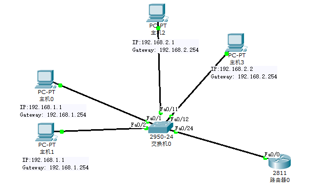
    操作:按照如图所示连接拓扑图
    image.png

    实验步骤

    (1)创建拓扑,配置设备
    添加一台路由器、一台交换机和四台主机

    PC0和PC1与交换机fa0/1、fa0/2 接口连接,划分在VLAN10中,IP分别为192.168.10.1、192.168.10.2,网关192.168.10.254。
    PC2和PC3与交换机fa0/11、fa0/12 接口连接,划分在VLAN20中,IP分别为192.168.20.1、192.168.20.2,网关192.168.20.254。
    交换机fa0/24端口与路由器fa0/1端口连接。

    (2)配置交换机

    
    /* Part 1 配置交换机 */
    Switch>enable
    Switch#configure terminal
    Switch(config)#hostname SA
    SA(config)#vlan 10
    SA(config-vlan)#vlan 20
    SA(config-vlan)#exit
    SA(config)#interface range fa0/1-fa0/2
    SA(config-if-range)#switchport access vlan 10
    SA(config-if-range)#interface range fa0/11-fa0/12
    SA(config-if-range)#switchport access vlan 20
    SA(config-if-range)#interface fa0/24
    SA(config-if)#switchport mode trunk
    SA(config-if)#switchport trunk allowed vlan all

/ Part 2 检查配置 / SA(config-if-range)#^Z (Ctrl+Z组合键) SA#show vlan … VLAN Name Status Ports


1 default active Fa0/3, Fa0/4, Fa0/5, Fa0/6 Fa0/7, Fa0/8, Fa0/9, Fa0/10 Fa0/13, Fa0/14, Fa0/15, Fa0/16 Fa0/17, Fa0/18, Fa0/19, Fa0/20 Fa0/21, Fa0/22, Fa0/23 10 VLAN0010 active Fa0/1, Fa0/2 20 VLAN0020 active Fa0/11, Fa0/12 …

(3)配置路由器
```bash
/* Part 1 配置路由器 */
Router>enable
Router#configure terminal
Router(config)#hostname RA
RA(config)#interface fa0/0.1
RA(config-subif)#encapsulation dot1Q 10
  // (1:在路由器上配置trunk的封装协议的命令:
  //  encapsulation [isl/dot1q] vlan#
  //  2:上面的路由器配置了dot1q中继封装,10是vlan 10。
  //  3:Trunk的封装类型一共有 ISL和802.1Q两种,而802.1Q在输入的时候为dot1q)
RA(config-subif)#ip address 192.168.10.254 255.255.255.0
RA(config-subif)#interface fa0/0.2
RA(config-subif)#encapsulation dot1Q 20
RA(config-subif)#ip address 192.168.20.254 255.255.255.0
RA(config-subif)#exit
RA(config)#interface fa0/0
RA(config-if)#shutdown
RA(config-if)#no shutdown     //(重启fa0/0接口)

/* Part 2 检查配置 */
RA>show interfaces fa0/0.1
...
  Internet address is 192.168.1.254/24
...
  Encapsulation 802.1Q Virtual LAN, Vlan ID 10
...

RA>show interfaces fa0/0.2
...
  Internet address is 192.168.2.254/24
...
  Encapsulation 802.1Q Virtual LAN, Vlan ID 20
...

(4)连通性测试

/* Part 1 PC0 Ping 自己网关 */
PC>ping 192.168.1.254

Pinging 192.168.1.254 with 32 bytes of data:

Reply from 192.168.1.254: bytes=32 time=11ms TTL=255
Reply from 192.168.1.254: bytes=32 time=12ms TTL=255
Reply from 192.168.1.254: bytes=32 time=11ms TTL=255
Reply from 192.168.1.254: bytes=32 time=12ms TTL=255

Ping statistics for 192.168.1.254:
    Packets: Sent = 4, Received = 4, Lost = 0 (0% loss),
Approximate round trip times in milli-seconds:
    Minimum = 11ms, Maximum = 12ms, Average = 11ms

/* Part 2 PC0 Ping PC1 */
PC>ping 192.168.1.2

Pinging 192.168.1.2 with 32 bytes of data:

Reply from 192.168.1.2: bytes=32 time=25ms TTL=128
Reply from 192.168.1.2: bytes=32 time=10ms TTL=128
Reply from 192.168.1.2: bytes=32 time=12ms TTL=128
Reply from 192.168.1.2: bytes=32 time=14ms TTL=128

Ping statistics for 192.168.1.2:
    Packets: Sent = 4, Received = 4, Lost = 0 (0% loss),
Approximate round trip times in milli-seconds:
    Minimum = 10ms, Maximum = 25ms, Average = 15ms

/* Part 3 PC0 Ping PC2 PC3网关 */
PC>ping 192.168.2.254

Pinging 192.168.2.254 with 32 bytes of data:

Reply from 192.168.2.254: bytes=32 time=11ms TTL=255
Reply from 192.168.2.254: bytes=32 time=14ms TTL=255
Reply from 192.168.2.254: bytes=32 time=11ms TTL=255
Reply from 192.168.2.254: bytes=32 time=12ms TTL=255

Ping statistics for 192.168.2.254:
    Packets: Sent = 4, Received = 4, Lost = 0 (0% loss),
Approximate round trip times in milli-seconds:
    Minimum = 11ms, Maximum = 14ms, Average = 12ms

/* Part 4 PC0 Ping PC2 */
PC>ping 192.168.2.1

Pinging 192.168.2.1 with 32 bytes of data:

Reply from 192.168.2.1: bytes=32 time=24ms TTL=127
Reply from 192.168.2.1: bytes=32 time=19ms TTL=127
Reply from 192.168.2.1: bytes=32 time=21ms TTL=127
Reply from 192.168.2.1: bytes=32 time=20ms TTL=127

Ping statistics for 192.168.2.1:
    Packets: Sent = 4, Received = 4, Lost = 0 (0% loss),
Approximate round trip times in milli-seconds:
    Minimum = 19ms, Maximum = 24ms, Average = 21ms

/* Part 5 PC0 Ping PC3 */
PC>ping 192.168.2.2

Pinging 192.168.2.2 with 32 bytes of data:

Request timed out.
Reply from 192.168.2.2: bytes=32 time=24ms TTL=127
Reply from 192.168.2.2: bytes=32 time=22ms TTL=127
Reply from 192.168.2.2: bytes=32 time=19ms TTL=127

Ping statistics for 192.168.2.2:
    Packets: Sent = 4, Received = 3, Lost = 1 (25% loss),
Approximate round trip times in milli-seconds:
    Minimum = 19ms, Maximum = 24ms, Average = 21ms

结论

由实验可知,划分VLAN后不同VLAN间的主机不能通信,可以使用路由器进行VLAN间通信。

注意: 1、主机需要配网关。 2、当出现Ping不通别的主机时,可以采用由近及远的检查方式,即依次Ping自己、自己的网关、对方主机的网关、对方主机以便于发现错误位置。

实验工程

单臂路由.zip

Cisco PT 案例八:配置基本ACL访问控制

环境

  • Cisco Packet Tracer 5.3
  • Windows 10

    操作

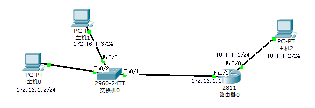
    操作:按照如图所示连接拓扑图
    image.png
    配置F0/1接口IP:

    R1(config)#interface fastEthernet 0/1        //进入Fa0/1
    R1(config-if)#ip address 172.16.1.1 255.255.255.0  //配置IP
    R1(config-if)#no shutdown                    //开启端口


    **
    配置F0/0接口IP:****

    R1(config)#interface fastEthernet 0/0        //进入Fa0/0
    R1(config-if)#ip address 10.1.1.1 255.255.255.0//配置IP
    R1(config-if)#no shutdown                    //进入Fa0/1


配置完成以后灯变绿了,在相互都可以ping通。
接下来给R1配上标准ACL,我个人建议一般正常下都是在进站口配置访问控制,用来减少路由器的工作负担,所以本文就是在进站口做了应用,也就是同时还要将访问控制运用在R1的Fa0/1端口。

R1(config)#access-list 10 deny host 172.16.1.2    //拒绝主机PC1的流量
R1(config)#access-list 10 permit any             //允许其他主机的流量
R1(config)#interface fastEthernet 0/1            //进入Fa0/1端口配置模式
R1(config-if)#ip access-group 10 in             //将ACL访问控制列表10应用于Fa0/1端口,同时在进站口就进行ACL的规则判断是否放行还是丢弃数据包

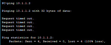
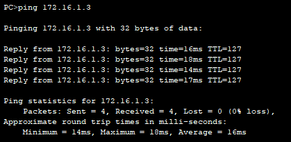
PC1和PC3不通:
image.png
PC3和PC1通:
image.png

Cisco PT 案例七:配置链路聚合 / 负载均衡

环境

  • Cisco Packet Tracer 5.3
  • Windows 10

    操作

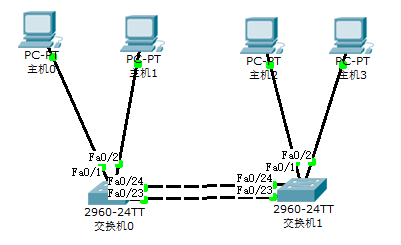
    操作:按照如图所示连接拓扑图
    image.png
    配置交换机0

Switch>enable Switch#configure terminal Switch(config)#hostname SA              (更改交换机名字) SA(config)#interface port-channel 1         (聚合通道1) SA(config-if)#exit SA(config)#interface fa0/22 SA(config-if)#channel-group 1 mode on      (开启聚合通道1) SA(config-if)#interface fa0/23 SA(config-if)#channel-group 1 mode on SA(config-if)#interface fa0/24 SA(config-if)#channel-group 1 mode on SA(config-if)#exit SA(config)#interface port-channel 1 SA(config-if)#switchport mode trunk            (交换机间链路类型为trunk) SA(config-if)#switchport trunk allowed vlan all     (允许所有VLAN通过)

配置交换机1
```bash
Switch>enable
Switch#configure terminal
Switch(config)#hostname SB
SB(config)#interface port-channel 1
SB(config-if)#exit
SB(config)#interface range fa0/22-fa0/24       (同时开启聚合通道1)
SB(config-if)#channel-group 1 mode on
SB(config-if)#exit
SB(config)#interface port-channel 1
SB(config-if)#switchport mode trunk
SB(config-if)#switchport trunk allowed vlan all

Cisco PT 案例六:交换机端口与Mac地址绑定

环境

  • Cisco Packet Tracer 5.3
  • Windows 10

    操作

    操作:按照如图所示连接拓扑图
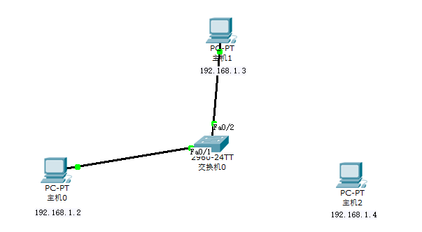
    image.png
    1、进入相应的接口
    (以端口1设置Mac地址绑定,PC0接1端口举例)

    Switch>enable
    Switch#config
    Configuring from terminal, memory, or network [terminal]?
    Enter configuration commands, one per line.  End with CNTL/Z.
    Switch(config)#
    Switch(config)#interface fastEthernet 0/1

    2、接口设为access模式

    Switch(config-if)#switchport mode access


3、启用安全端口

Switch(config-if)#switchport port-security
(查看mac-address绑定的几种方式,分别为静态绑定和粘滞绑定)
Switch(config-if)#switchport port-security mac-address ?
H.H.H   48 bit mac address
sticky  Configure dynamic secure addresses as sticky


第一种:动态配置

第二种:静态配置

(其中代码的最后一列为主机的Mac地址。寻找方法:单击主机→配置→fastEthernet→mac地址。)

Switch(config-if)#switchport port-security mac-address 0001.C94E.1321


设置完成后,用主机pc0 ping pc2,然后可以在特权模式下通过以下命令查看以下(ctrl+z,快速回到特权模式下)

Switch#show port-security address

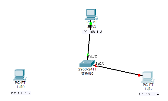
若将pc0与端口1的连线断掉,改用pc3接端口1。在进行 pc3 ping pc2 不通(图示如下)
image.png
改回pc1依然不通,需重启路由器该端口

Switch(config-if)#shutdown

%LINK-5-CHANGED: Interface FastEthernet0/1, changed state to administratively down
Switch(config-if)#no shutdown

%LINK-5-CHANGED: Interface FastEthernet0/1, changed state to up

%LINEPROTO-5-UPDOWN: Line protocol on Interface FastEthernet0/1, changed state to up

Switch(config-if)#

Cisco PT 案例五:VLAN(Trunk模式实践)

环境

  • Cisco Packet Tracer 5.3
  • Windows 10

    操作

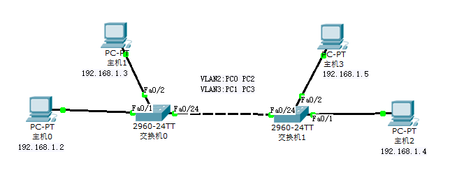
    操作:按照如图所示连接拓扑图
    image.png
    实验步骤

  1. 创建VLAN 2和VLAN 3,财务部对应VLAN 2,销售部对应VLAN 3
  2. 将部门PC对应端口划分到相应的VLAN中
  3. 为交换机配置VTP模式及VTP域名
  4. 配置交换机间互联的端口为Trunk类型


PC设置

192.168.1.2        //PC0
192.168.1.3        //PC1
192.168.1.4        //PC2
192.168.1.5        //PC3
//子网掩码和网关
255.255.255.0
192.168.1.1

Switch0配置

Switch>en
Switch#conf t
Switch(config)#vlan 2                  //创建VLAN 2
Switch(config-vlan)#name Finance_Dept         //将该VLAN命名为Finance_Dept
Switch(config-vlan)#vlan 3             //创建VLAN 2
Switch(config-vlan)#name Sales_Dept          //将该VLAN命名为Sales_Dept
Switch(config-vlan)#exit
Switch(config)#inter f0/1
Switch(config-if)#switchport access vlan 2        //将该端口划分到VLAN 2
Switch(config-if)#exit
Switch(config)#inter f0/2
Switch(config-if)#switchport access vlan 3        //将该端口划分到VLAN 3
Switch(config-if)#exit
Switch(config)#inter f0/24
Switch(config-if)#switch mode trunk               //将端口配置为Trunk模式
Switch(config-if)#end
Switch#show vlan brief                //显示VLAN配置信息
Switch#vlan database                  //进入VLAN子模式
Switch(vlan)#vtp server                      //设置VTP模式为server
Switch(vlan)#vtp domain vtp0                 //设置VTP域名为vtp0
Switch(vlan)#exit
Switch#show vtp status                       //查看VTP配置信息

Switch1配置

Switch>en
Switch#vlan database                //进入VLAN子模式
Switch(vlan)#vtp client                     //设置VTP模式为client
Switch(vlan)#vtp domain vtp0                //设置VTP域名为vtp0,此处不填亦可
Switch(vlan)#exit
Switch#show vtp status             //查看VTP配置信息
Switch#show vlan brief             //显示VLAN配置信息
Switch#conf t
Switch(config)#inter f0/1
Switch(config-if)#switchport access vlan 2        //将该端口划分到VLAN 2
Switch(config-if)#exit
Switch(config)#inter f0/2
Switch(config-if)#switchport access vlan 3        //将该端口划分到VLAN 3
Switch(config-if)#exit
Switch(config)#inter f0/24
Switch(config-if)#switch mode trunk               //将端口配置为Trunk模式
Switch(config-if)#end
Switch#show r

测试

PC0(命令提示符CMD下)
ping 192.168.1.3           //链路不通
ping 192.168.1.4           //链路通
PC1(命令提示符CMD下)
ping 192.168.1.4           //链路不通
ping 192.168.1.5           //链路通

Cisco PT 案例四:VLAN(Access模式实践)

环境

  • Cisco Packet Tracer 5.3
  • Windows 10

    操作

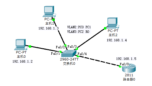
    操作:按照如图所示连接拓扑图
    image.png
    实验步骤

  1. 创建VLAN 2和VLAN 3
  2. 将部门PC对应端口划分到相应的VLAN中

PC设置

192.168.1.2        //PC0
192.168.1.3        //PC1
192.168.1.4        //PC2
192.168.1.5        //R0
//子网掩码和网关
255.255.255.0
192.168.1.1

Switch0配置


Switch>en                       // 进入特权模式
Switch#conf t               // 进入全局配置模式命令缩写
Enter configuration commands, one per line.  End with CNTL/Z.
Switch(config)#vlan 2
Switch(config-vlan)#exit
Switch(config)#vlan 3
Switch(config-vlan)#exit
Switch(config)#inter f0/1
Switch(config-if)#switchport access vlan 2
Switch(config-if)#exit
Switch(config)#inter f0/2
Switch(config-if)#switchport access vlan 2
Switch(config-if)#exit
Switch(config)#inter f0/3
Switch(config-if)#switchport access vlan 3
Switch(config-if)#exit
Switch(config)#inter f0/4
Switch(config-if)#switchport access vlan 3
Switch(config-if)#exit
Switch(config)#exit
Switch#
%SYS-5-CONFIG_I: Configured from console by console

Switch#show vlan brief

VLAN Name                             Status    Ports
---- -------------------------------- --------- -------------------------------
1    default                          active    Fa0/5, Fa0/6, Fa0/7, Fa0/8
                                                Fa0/9, Fa0/10, Fa0/11, Fa0/12
                                                Fa0/13, Fa0/14, Fa0/15, Fa0/16
                                                Fa0/17, Fa0/18, Fa0/19, Fa0/20
                                                Fa0/21, Fa0/22, Fa0/23, Fa0/24
                                                Gig1/1, Gig1/2
2    VLAN0002                         active    Fa0/1, Fa0/2
3    VLAN0003                         active    Fa0/3, Fa0/4
1002 fddi-default                     active    
1003 token-ring-default               active    
1004 fddinet-default                  active    
1005 trnet-default                    active    
Switch#

测试

PC0(命令提示符CMD下)
ping 192.168.1.3           //链路通
ping 192.168.1.4           //链路不通
PC2(命令提示符CMD下)
ping 192.168.1.2           //链路不通
ping 192.168.1.5           //链路通

Cisco PT 案例三:端口使能/禁用

环境

  • Cisco Packet Tracer 5.3
  • Windows 10

    操作

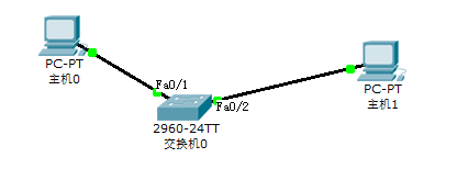
    操作:按照如图所示连接拓扑图
    image.png

    
    # 进入特权模式
    Switch>enable
    # 进入全局配置模式
    Switch#configure terminal
    Enter configuration commands, one per line.  End with CNTL/Z.
    Switch(config)#
    # 进入端口
    Switch(config)#interface FastEthernet0/1
    Switch(config-if)#
    # 禁用
    Switch(config-if)#shutdown

%LINK-5-CHANGED: Interface FastEthernet0/1, changed state to administratively down Switch(config-if)# %LINEPROTO-5-UPDOWN: Line protocol on Interface FastEthernet0/1, changed state to down

使能

Switch(config-if)#no shutdown

%LINK-5-CHANGED: Interface FastEthernet0/1, changed state to up

%LINEPROTO-5-UPDOWN: Line protocol on Interface FastEthernet0/1, changed state to up

Switch(config-if)#

Cisco PT 案例二:为路由器配置并连接SSH

1. 案例目标

通过本案例,你可以掌握如下技能:

  1. 配置 SSH

  2. 使用 SSH 访问路由器

    2. 背景知识

    过去对路由器的远程管理访问一般使用 TCP 端口 23 上的 Telnet。但 Telnet 是在安全不是问题的年代开发的。为此,所有 Telnet 流量以明文的形式转发。 SSH 已经替代了 Telnet,作为远程路由器连接管理的最佳工具,它提供强大的私密性和会话的集成。SSH 使用 TCP 端口 22。它提供类似出站 Telnet 连接的功能,但连接是加密的。通过认证和加密,SSH 允许在不安全的网络中进行安全的通信。想在路由器上激活 SSH,必须配置以下参数:

  • Hostname(主机名)

  • Domain name(域名)

  • Asymmetrical keys(非对称密钥)

  • Local authentication(本地验证)

    3. 设备与拓扑

    环境:Cisco Packet Tracer 5.3
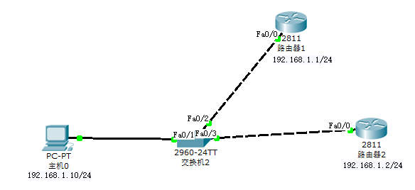
    设备:1 台普通 PC,1 台 2950T-24 交换机,2 台 2811 路由器。
    拓扑:如下图。
    image.png

    4. 操作步骤

    步骤 1:按拓扑图添加设备与连接。
    步骤 2:配置路由器接口。

    打开路由器的 Config配置页面,按拓扑图上的标注分别配置两个路由
    器的显示名、主机名和接口 Fa0/0 的 IP 地址,并注意激活该接口。
    步骤 3:配置 PC 的 IP 地址和网关。

    用 PC 的 IP configuration 程序配置其 IP 地址和网关。
    步骤 4:在 R1 上配置 SSH
    1) 配置域名

R1#conf t 
R1(config)#ip domain-name cisco.com 
R1(config)#


2) 配置非对称密钥

R1(config)#crypto key generate rsa 
# 当提示密钥长度时,输入 1024。注:缺省为 512。


3) 配置用于认证的登录用户名及口令

R1(config)#username admin password cisco


4) 配置 SSH 版本

R1(config)#ip ssh version 2
  1. 配置 SSH 会话最大空闲超时值和 SSH 连接认证重试次数
    R1(config)#ip ssh time-out ?  
    <1-120> SSH time-out interval (secs)  
    R1(config)#ip ssh time-out 60 //最大空闲超时:60 秒
    R1(config)#ip ssh authentication-retries ?  
    <0-5> Number of authentication retries  
    R1(config)#ip ssh authentication-retries 2 //认证重试次数:2 次
    R1(config)#
  2. 在 VTY 线路上禁用 Telnet,并激活 SSH。
    R1(config)#line vty 0 4  
    R1(config-line)#no transport input all //禁用所有流量
    R1(config-line)#transport input ssh //允许 SSH 流量
    R1(config-line)#login local //要求本地认证

    步骤 5:在 R2 上重复步骤 4,配置 SSH。
    步骤 6:在 R1 上验证 SSH 的配置及运行
    1) 验证 SSH 版本及其他设置

    R1#sh ip ssh  
    SSH Enabled - version 2.0  
    Authentication timeout: 60 secs; Authentication retries: 2  
    R1#
  3. 验证 SSH 是否在运行
    R1#sh ssh  
    %No SSHv2 server connections running.  
    %No SSHv1 server connections running.  
    R1#

    步骤 7:在 R2 上重复步骤 6,验证 SSH 的配置及运行。
    步骤 8:测试 SSH
    1) 在 PC0 的命令行窗口中对 R1 和 R2 分别进行 telnet 和 ssh 的测试,
    如图 5-1。telnet 应失败,而 ssh 应成功。

    
    PC>telnet 192.168.1.1
    Trying 192.168.1.1 ...Open

[Connection to 192.168.1.1 closed by foreign host] PC>tennet 192.168.1.2 Invalid Command.

PC>ssh -l admin 192.168.1.1 Open Password:

R1>exit

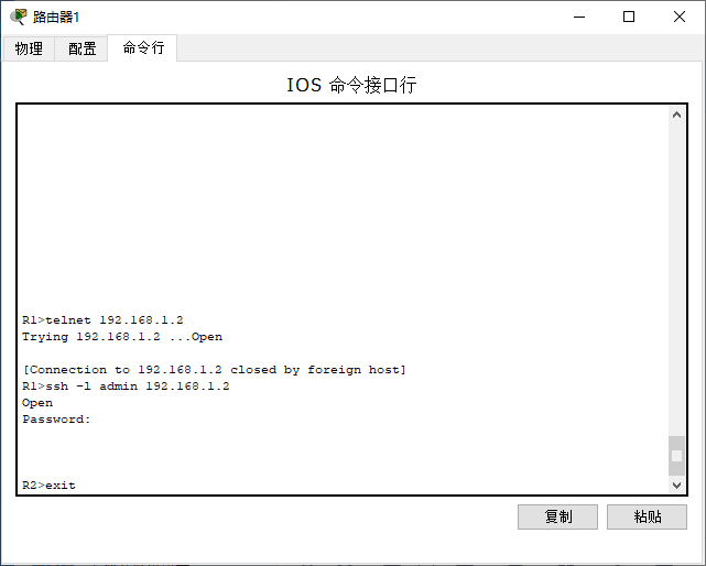
![image.png](https://cdn.nlark.com/yuque/0/2020/png/376635/1592190949265-0d5739cc-5da0-48b6-a6d2-17e8d57e751f.png#align=left&display=inline&height=514&margin=%5Bobject%20Object%5D&name=image.png&originHeight=514&originWidth=641&size=28028&status=done&style=none&width=641)<br />2) 在 R1 中对 R2 进行测试,telnet 应失败,而 ssh 应成功。反之亦然。<br />如图 5-2。
```bash
R1>telnet 192.168.1.2
Trying 192.168.1.2 ...Open

[Connection to 192.168.1.2 closed by foreign host]
R1>ssh -l admin 192.168.1.2
Open
Password: 

R2>

image.png

Cisco PT案例一:为交换机配置并连接TELNET

Telnet协议是TCP/IP协议族中的一员,是Internet远程登陆服务的标准协议和主要方式。它为用户提供了在本地计算机上完成远程主机工作的能力。在终端使用者的电脑上使用telnet程序,用它连接到服务器。终端使用者可以在telnet程序中输入命令,这些命令会在服务器上运行,就像直接在服务器的控制台上输入一样。可以在本地就能控制服务器。要开始一个telnet会话,必须输入用户名和密码来登录服务器。Telnet是常用的远程控制Web服务器的方法。

环境

  • Cisco Packet Tracer 5.3
  • Windows 10

    操作

    操作:按照如图所示连接拓扑图
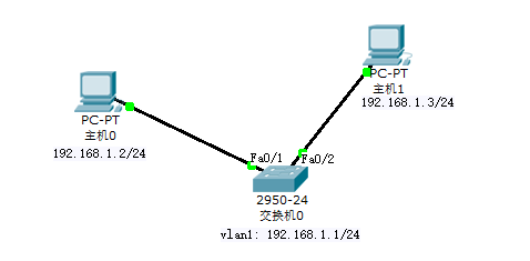
    image.png
    (1)配置PC IP

    PC0 设置
    192.168.1.2/24
    PC1 设置
    192.168.1.3/24

    (2)配置交换机VLAN1 IP

    
    /* part1 为vlan配置ip并开启vlan */
    Switch>enable
    Switch#configure terminal
    Enter configuration commands, one per line.  End with CNTL/Z.
    Switch(config)#interface vlan 1
    Switch(config-if)#ip address 192.168.1.1 255.255.255.0
    Switch(config-if)#no shutdown

%LINK-5-CHANGED: Interface Vlan1, changed state to up

%LINEPROTO-5-UPDOWN: Line protocol on Interface Vlan1, changed state to up Switch(config-if)#

/ Part2 查看已配置的IP / Switch(config-if)#^Z Switch# %SYS-5-CONFIG_I: Configured from console by console

Switch#show running-config … interface Vlan1 ip address 192.168.1.1 255.255.255.0

/ Part3 开启Vlan / Switch#conf t Enter configuration commands, one per line. End with CNTL/Z.
Switch(config)#interface vlan 1 Switch(config-if)#no shutdown

/ Part4 查看Vlan状态 / Switch(config-if)#^Z Switch# %SYS-5-CONFIG_I: Configured from console by console

Switch#show interfaces vlan 1 Vlan1 is up, line protocol is up …

**(3)配置交换机本地登录口令**

/ Part 1 设置明文密码/ Switch#conf t Enter configuration commands, one per line. End with CNTL/Z. Switch(config)#enable password 123 // 注:取消密码可用no enable password

/ Part 2查看设置的密码 / Switch(config)#^Z Switch# %SYS-5-CONFIG_I: Configured from console by console

Switch#show running-config … enable password 123 …

**(4)配置交换机远程登陆及验证**

Switch#conf t Enter configuration commands, one per line. End with CNTL/Z. Switch(config)#line vty 0 Switch(config-line)#password 123 //(Telnet密码为123) Switch(config-line)#login local //(login是开启远程登录密码验证,login local不但要求TELNET密码,还要求提供用户名) Switch(config-line)#

**(5)添加可远程登陆交换机的用户**

/ Part 1 添加用户 / Switch#conf t Enter configuration commands, one per line. End with CNTL/Z. Switch(config)#line vty 0 Switch(config-line)#password 123 Switch(config-line)#login local Switch(config-line)# Switch(config-line)#exit Switch(config)#username admin password admin

/ Part 2 查看添加的用户 / Switch(config)#exit Switch# %SYS-5-CONFIG_I: Configured from console by console

Switch#show running-config … username admin password 0 admin …


<br />**(6)测试连接**

// 在PC0的CMD中测试 / Part 1 Ping交换机 / PC>ping 192.168.1.1

Pinging 192.168.1.1 with 32 bytes of data:

Reply from 192.168.1.1: bytes=32 time=5ms TTL=255 Reply from 192.168.1.1: bytes=32 time=5ms TTL=255 Reply from 192.168.1.1: bytes=32 time=6ms TTL=255 Reply from 192.168.1.1: bytes=32 time=6ms TTL=255

Ping statistics for 192.168.1.1: Packets: Sent = 4, Received = 4, Lost = 0 (0% loss), Approximate round trip times in milli-seconds: Minimum = 5ms, Maximum = 6ms, Average = 5ms

/ Part 2 Telnet 连接交换机 / PC>telnet 192.168.1.1 Trying 192.168.1.1 …Open

User Access Verification

Username: admin Password: Switch>

**(7)配置多用户连接**

// 在PC0连接的前提下,再使用PC1尝试连接 / Part 1 PC1 Ping Switch / PC>ping 192.168.1.1

Pinging 192.168.1.1 with 32 bytes of data:

Request timed out. Reply from 192.168.1.1: bytes=32 time=6ms TTL=255 Reply from 192.168.1.1: bytes=32 time=6ms TTL=255 Reply from 192.168.1.1: bytes=32 time=5ms TTL=255

Ping statistics for 192.168.1.1: Packets: Sent = 4, Received = 3, Lost = 1 (25% loss), Approximate round trip times in milli-seconds: Minimum = 5ms, Maximum = 6ms, Average = 5ms

/ Part 2 PC1 Telnet 连接Swithc / PC>telnet 192.168.1.1 Trying 192.168.1.1 …Open

[Connection to 192.168.1.1 closed by foreign host] // 连接失败,因为交换机vty设置只能同时打开一个会话,下面设置一下,使两台PC可同时访问

/ Part 3 修改Tenlet配置 / // 可直接在PC0直接进行 Switch#conf t Enter configuration commands, one per line. End with CNTL/Z. Switch(config)#line vty 0 1 Switch(config-line)#password 123 Switch(config-line)#^Z

/ Part 4 重新尝试Part 2 / PC>telnet 192.168.1.1 Trying 192.168.1.1 …Open

User Access Verification

Password: Switch> // 成功